IMXCode: blend an image into a QR code
Presentation
I was designing a business card for one of my project, but the perfectionist part of my personality couldn’t accept a plain QR code on my business card. Instead I wanted a QR code unique to me. Thus I made another side project instead of just printing my business card: IMX Code.
IMX Code is a web app I implemented from scratch to blend an image into a QR code that still scans. It is a static site hosted on Cloudflare Pages. There is no backend, and nothing you type or upload ever leaves your device.
| Plain QR code | The same link, blended with an image |
|---|---|
 |  |
Both encode https://example.com/hello and both decode.
This article focuses on the ideas specific to the QR generator: how a picture can be drawn into a code without touching its data, how I decide whether the result scans, and the tradeoffs I had to make between looks and reliability. The page, the languages, the analytics and the branded frame are adapted from standard patterns, so I leave them out.
Requirements
- A code must look like the picture, not like a black-and-white grid with a logo pasted on it.
- Scanning is the product. A code that looks good but does not scan is a bug, so the app must check
its own output instead of hoping:
- the exact text must decode, not just “something”
- it must still decode from a low-resolution copy, as a phone camera sees it
- when it doesn’t, the app must fix the code itself rather than hand over a broken one
- The payload and the error-correction data must stay untouched, so any standard scanner can read the code.
- Privacy by design, which has consequences on the architecture:
- everything runs in the browser, with no upload and no server-side rendering
- the generator is pure logic that does not depend on the page, so it can be tested on its own exactly as it runs in the browser
- The same code must be available as a PNG and as a vector SVG, without the two renderers drifting apart.
- Any text works: URLs, Unicode, Wi-Fi strings, long content.
- Whatever image the visitor drops (a logo, a photo, a transparent PNG, a nearly black picture) must give a code that decodes.
- Every option the visitor can change must be safe: no combination of settings should crash the generator.
Tech stack
- Languages: TypeScript
- Frontend: Astro (static output), vanilla TypeScript, no UI framework, jsQR
- Generator:
qrcode-generatorfor the encoding, everything else written by hand (halftone model, raster and SVG renderers, anti-aliasing, image fitting) - Tests: Vitest, fast-check (property tests), ZXing (C++, via
zxing-wasm) as a second decoder, resvg to rasterise the SVG independently, Playwright for end-to-end - Infrastructure: Cloudflare Pages, self-hosted cookieless Umami analytics
Links
The idea
Many “artistic QR” tools change the modules themselves, or paint the image over the code and hope. I chose a different trade. I never change a module’s value. The payload and the Reed-Solomon codewords come out of a standard encoder untouched. I only change how each module is drawn.
A scanner doesn’t look at whole modules. It samples the pixel at the centre of each module and asks “dark or light?”. So I draw:
- the image as a backdrop, filling the whole code area, and
- on top of it, one dot at the centre of every module. The dot’s brightness is forced to the dark side or the light side, depending on the module’s value.
The dot keeps the image’s hue. A dark module over a red area becomes a dark red dot. A light module becomes a pale red dot. The image shows between the dots, so the eye sees the picture and the scanner sees the dot centres.
| Plain QR (reference) | Dots only, no image | Dots over the image |
|---|---|---|
|  | |
All three encode https://example.com/hello and decode.
The pipeline
flowchart LR
    TXT["text"] --> ENC["Encoding<br/>module matrix"]
    ENC --> CLS["Classification<br/>module kinds"]
    IMG["image"] --> FIT["Fitting<br/>square picture"]
    OPT["Options<br/>validated settings"]
    CLS --> MOD["Model<br/>backdrop + shapes"]
    FIT --> MOD
    OPT --> MOD
    MOD --> RAS["Raster renderer<br/>RGBA pixels"]
    MOD --> VEC["Vector renderer<br/>SVG with embedded backdrop"]
    RAS --> VER["Verification<br/>decode check"]
    VER -->|"fails: next rung"| ENC
A generation step drives the loop from the encoding to the verification, and the arrow back is the retry with a stronger set of options.
Each stage is a small, independent step with plain data in and out:
| Stage | Job |
|---|---|
| Options | The settings, their defaults, and a validation step that clamps every value into its valid range. |
| Encoding | Text and error-correction level in, a grid of dark and light modules out. |
| Classification | Labels every module: finder, separator, alignment, timing, format, version, dark, data. |
| Fitting | Fits the picture into a square (cover or contain), alpha-aware. |
| Colour | Moves a colour to a target luma and keeps its hue. |
| Model | Turns matrix, image and options into one backdrop raster plus an ordered list of shapes. |
| Raster and vector renderers | Two independent renderers of the same model. |
| Verification | Decodes the result to check it scans. |
| Generation | Runs the whole thing and tunes it until it scans. |
The renderers are the reason I have a model in the middle. It is plain data (rectangles, circles, one raster), so I wrote the PNG painter and the SVG writer separately and they can’t drift apart. A test rasterises the SVG with an independent renderer (resvg) and decodes that too.
Encoding
I rely on a standard QR encoder for the encoding itself, and add three things on top:
- UTF-8. Encoders commonly default to Latin-1 and silently truncate anything else. I force UTF-8, which is the QR convention. A test with CJK text guards it.
- Mode selection. Pure digits use Numeric mode. Text that fits the 45-character alphabet uses Alphanumeric. Everything else uses Byte. This keeps the version as small as possible, which means bigger modules and an easier scan.
- Minimum version. If the user asks for a larger version than the content needs, I build at that version. The spare capacity becomes standard padding, so the decoded text is identical. The code just has more, smaller modules, which gives a finer halftone. If the content needs more than the requested version, I fall back to the automatic size rather than failing.
The output is a square grid of modules (1 = dark) and the version number.
Classification
Not every module can be treated as a dot. The finder patterns (the three big eyes) and alignment patterns are what the decoder uses to find and straighten the code. They have to stay solid. So I build a map of module kinds for a given version using the ISO 18004 layout:
- timing lines on row 6 and column 6 (drawn first, so more specific kinds overwrite them where they cross),
- three 7×7 finders with their one-module separators,
- the format information strips and the single always-dark module,
- alignment centres from the Annex E table, skipping the three that would collide with finders,
- version blocks for version 7 and up.
Everything left is data. That map decides how each module is drawn.
Fitting the image
The picture is sampled into a square, fully opaque image with bilinear filtering on premultiplied alpha. Transparent logos therefore don’t bleed their hidden colour into the edges. They are composited over the background colour.
- Cover crops to fill the square. Contain letterboxes, and the bars show the background.
- The image margin insets the image inside the code and leaves the edge empty. It is not the same as the quiet zone. The quiet zone is the blank border outside the code.
| Image margin 0 | Image margin 15 % |
|---|---|
 |  |
Building the model
This stage does the real work. The cell (pixels per module) is always a whole number:
Whole-pixel cells keep every dot centre on a predictable pixel grid, which is worth more than hitting the requested size exactly. Sometimes the output is a few pixels smaller than asked, and I accept that.
The backdrop
The fitted image is blended toward the background colour by the image strength:
where s is the image strength, applied per pixel p and per colour channel. So s = 1 is the full picture and s = 0.5 is a faded one. At s = 0 there is no backdrop.
One dot per data module
For each data module I take the average image colour over that module’s cell. Then I push its luma.
Luma is Rec. 709 on gamma-encoded values, the same weights jsQR uses to binarise:
With k the contrast setting, the two limits are
so the default k = 0.7 gives L_{\mathrm{dark}} = 0.15 and L_{\mathrm{light}} = 0.85. For the average colour c of the module’s cell:
A dot is only ever moved away from the middle: a colour that is already dark enough stays as it is. The adjust function moves a colour to a target luma t while keeping its hue. It scales toward black to darken and mixes toward white to lighten:
applied to each channel, then rounded and clamped to [0, 255]. The contrast is therefore the distance from mid-grey that I guarantee between a “dark” dot and a “light” dot, whatever the image looks like underneath.
In solid-colour mode the dots just use the foreground and background colours.
The dot scale is the dot’s diameter as a fraction of the module, and the dot style is circle or square.
| Dot scale 0.4 | Dot scale 0.6 (default) | Dot scale 0.85 |
|---|---|---|
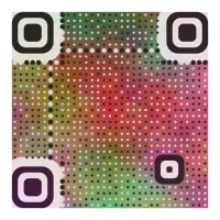 | 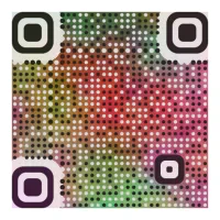 | 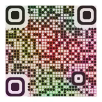 |
Bigger dots cover more of the picture and are easier to scan. Smaller dots show more image. That is the main trade-off, and the next section is about managing it.
| Contrast 0.3 (does not scan) | Contrast 0.7 (default) | Contrast 1 |
|---|---|---|
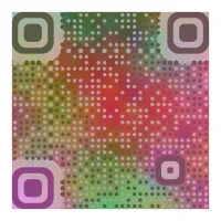 | 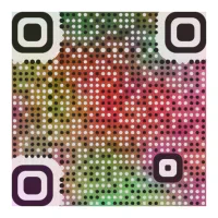 | 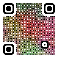 |
I’m showing the 0.3 image on purpose. In my check at full size jsQR could not decode it, even though the downscaled copy did. Pretty is easy, and a code that fails is a bug, so the verify step exists.
| Image strength 0 (does not scan) | Image strength 0.5 | Image strength 1 (default) |
|---|---|---|
 | 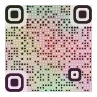 | 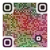 |
At strength 0 in image-colour mode there is no backdrop, and the dots are just coloured specks on a flat background. Neither decode check passed in this run. Solid-colour mode with a plain background is the fix for that look.
Finder and alignment patterns
These are drawn solid, as concentric shapes, and tinted from the image:
- the outer ring is dark, with a hole where the light ring goes, so the backdrop shows through,
- the 3×3 core is dark,
- the colour is the dark-limited average of the image under the pattern.
The light ring is not flat white. The backdrop is lifted: every pixel within reach of the pattern is raised to at least the light luma. That keeps the image visible and smooth, but it can never read as dark. For finders, the lifted area also covers the separator, at least a module and a half wide, and it follows the eye’s outline. A rounded eye doesn’t get light square corners. Alignment patterns have no separator in the spec, so I lift only their light ring.
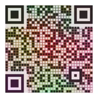
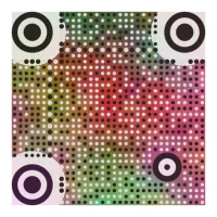
The eye style can be square, rounded or circle. Only the outline changes, not the geometry a scanner relies on.
| Square eyes + square dots | Rounded eyes (default) | Circle eyes |
|---|---|---|
 | |  |
Timing lines and format info
Row 6 and column 6 alternate dark and light so the decoder can work out the module size. The format strips sit next to the eyes and tell it the error-correction level and mask. A misread there fails the whole code. So a minimum timing-dot size (default 0.8 of the module) forces those modules to be drawn at least that large, even when data dots are small.
It looks slightly uneven, but I measured it. At about 3 px per module, ZXing read roughly half of small-dot codes without it and almost all with it. A dedicated test pins this, and I don’t remove it to make the dots uniform.
| Dot scale 0.4, timing minimum 0.3 | Dot scale 0.4, timing minimum 0.8 |
|---|---|
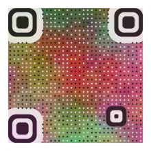 | 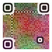 |
The difference is easiest to see along the dotted lines between the eyes.
Output
The model is a background colour, an optional backdrop raster, and an ordered list of shapes. A shape is a rounded rectangle or a circle, with a fill and an optional hole that is cut out of it.
Rendering
Raster. I fill the background, copy in the backdrop, then paint each shape. Anti-aliasing uses a signed-distance function. For a pixel centre at signed distance d from the shape edge (negative inside), the coverage is
and the pixel becomes (1 - \alpha)\,\mathrm{old} + \alpha\,\mathrm{fill}. A hole multiplies the shape’s coverage by 1 - \alpha_{\mathrm{hole}}, which gives clean ring edges without needing a path rasteriser.
SVG. The same model becomes a vector document: the background rectangle, one embedded image for the backdrop, then a circle or rectangle per shape. Shapes with holes become a single even-odd path. The backdrop is encoded as an image and capped at 768 px per side to keep files reasonable.
Making sure it scans
A halftone can easily look fine and fail on a phone, so I check each result.
The verification step decodes the rendered raster with jsQR (inverted codes are not accepted, because most phones can’t read them). A code passes only if the exact text decodes at both:
- full size, and
- a box-downsampled copy where each module is about 4 px wide, that is a scale factor of 4 / \mathrm{cell}. That is a cheap stand-in for a phone camera that sees fewer pixels per module.
flowchart LR
    R["rendered raster"] --> F["decode at full size"]
    R --> D["box-downsample to 4 px / module"] --> G["decode"]
    F --> C{"both return<br/>the exact text?"}
    G --> C
    C -->|yes| OK["ok"]
    C -->|no| KO["fails"]
Auto-tune
Generation builds, renders, verifies, and if it fails and auto-tune is on, it tries the next rung of a tuning ladder. Each rung only makes the code easier to scan than what the user asked for:
| Rung | Changes |
|---|---|
| 0 | exactly the user’s options |
| 1 | contrast ≥ 0.85, dots ≥ 0.7 |
| 2 | contrast ≥ 0.95, dots ≥ 0.8, timing dots ≥ 0.9, image ≤ 85 % |
| 3 | contrast 1, dots ≥ 0.9, timing dots 1, image ≤ 60 %, quiet zone ≥ 3, square eyes |
| 4 | plain black-on-white, square dots, full size, quiet zone ≥ 4 |
flowchart LR
    R0["Rung 0<br/>user's options"] -->|fails| R1["Rung 1<br/>more contrast, bigger dots"]
    R1 -->|fails| R2["Rung 2<br/>+ timing dots, less image"]
    R2 -->|fails| R3["Rung 3<br/>full contrast, square eyes"]
    R3 -->|fails| R4["Rung 4<br/>plain black on white"]
    R0 -->|scans| DONE["done"]
    R1 -->|scans| DONE
    R2 -->|scans| DONE
    R3 -->|scans| DONE
    R4 -->|always scans| DONE
The last rung is an ordinary QR code, so the loop always ends with something that decodes. It never lowers the minimum version, the error-correction level, the fit mode or the image margin, because those are the user’s structural choices. Duplicate rungs are dropped by comparing their validated options. The result reports whether the settings were changed and how many attempts it took, so the interface can tell the user that their settings were strengthened.
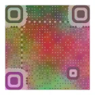
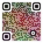
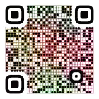
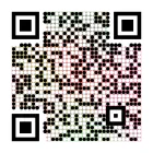
Here is the ladder on a deliberately weak start (dot scale 0.35, contrast 0.3). Rung 0 fails the full-size decode. In my run generation stopped after two attempts, at rung 1.
| Rung 0 (fails) | Rung 1 | Rung 2 | Rung 3 | Rung 4 |
|---|---|---|---|---|
 |  |  |  |  |
Error correction and version (the density knobs)
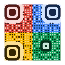
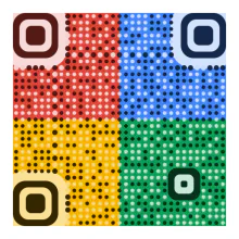
The error-correction level is the Reed-Solomon level (L, M, Q, H) and defaults to H. Halftoning damages a lot of pixels, and H gives the most room for mistakes. The price is capacity: the same text needs a bigger version, so modules are smaller. The minimum version forces more modules deliberately.
| Error correction L (version 2) | Error correction H (version 4, default) |
|---|---|
 |  |
Because the cell is a whole number, a higher version shrinks the cell at a fixed output size. At 480 px the same link gives these:
| Minimum version 1 (v4, 12 px/module) | Minimum version 10 (7 px) | Minimum version 20 (4 px, the floor) |
|---|---|---|
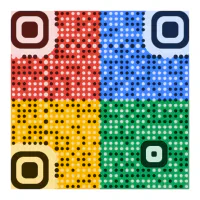 | 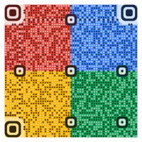 |  |
More modules give a finer picture, but each module is smaller on screen, and the 4 px minimum cell stops it getting too small to read.
Different pictures
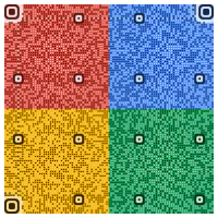
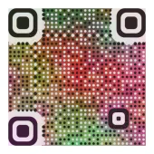
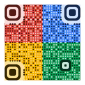
The same defaults on different inputs, from a logo to a photo-like texture. Each decoded in my run.
| Gradient logo | Texture | Four colours | Dark on yellow |
|---|---|---|---|
 |  |  |  |
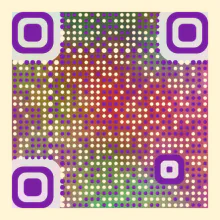
And solid-colour mode with custom colours, which ignores the image’s hues:
Options are always safe
The renderer never defends against bad input, because the options are validated first. The validation:
- fills defaults, treating an explicitly empty value as “not set”,
- clamps every number into its range and rounds the integer ones,
- rejects unknown choices,
- falls back to the default for invalid hex colours,
- swaps foreground and background if the foreground isn’t darker, so you can’t ask for an inverted code.
How I test it
Scanning is the product, so the tests are mostly about decoding:
- Round-trip corpus. Every fixture image times every sample text (short URL, long URL, Unicode, Wi-Fi string) must decode with the default options and no tuning. I fix the renderer when this fails and never edit the test.
- Two decoders. jsQR and ZXing (C++, via
zxing-wasm, offline) both have to read the output. They disagree in useful ways. - Structural check. A test asserts that every module centre pixel is on the correct side of mid-grey for every fixture. This doesn’t depend on any single decoder’s quirks.
- SVG vs raster. The SVG is rasterised by resvg and decoded, and compared with the raster output.
- Property tests (
fast-check) across content, image and options. - Fixtures are deterministic and synthetic: logos, a gradient, noise, very dark, very bright, mid-grey, transparent, a 16 px image, and wide and tall banners. They are chosen to break the luma logic.
What I can’t automate is a real phone camera. Before a release I scan a few outputs from a screen by hand.
Things to remember
- Encode text as UTF-8, never Latin-1.
- Don’t “fix” the larger timing dots. They are what makes small-dot codes readable.
- The image margin and the quiet zone are different things.
- Output size is \mathrm{cell} \cdot (\mathrm{modules} + 2 \cdot \mathrm{quietZone}). It can be a little smaller than the requested size.
- Adding an option means validating it, using it in the model, and proving with a test that it takes effect.